System architecture
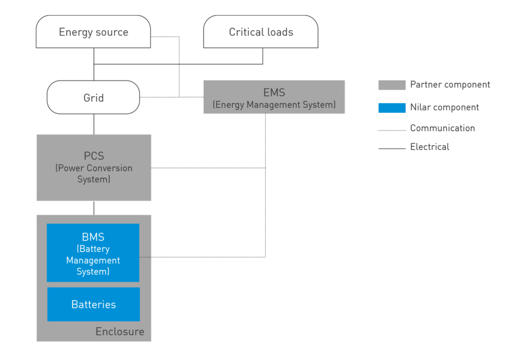
Nilar provides a complete solution of both hardware and software interfaces between the battery and external control systems. It includes an embedded circuit board design with electrical control posibilites as well as measurement devices. It also includes redundancy for the monitoring and safety of the batteries through a separate circuit.
Overview
The Nilar Battery Management System (BMS) monitors, controls and protects the batteries and its environment to maintain a long service life. Through its combination of software and hardware, the fine-tuned management system optimizes battery operation for best-in-class reliability, safety and efficiency at all times. Remote access is needed for support, troubleshooting and software updates.
BMS Circuit board descriptions
The BMS consists of the BMS Master Unit, the String Cluster Unit, the Integrated Monitoring Unit, the Fan Control Unit and a Humidity LED Interface.
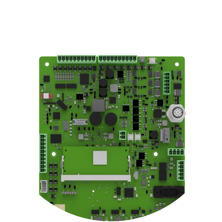
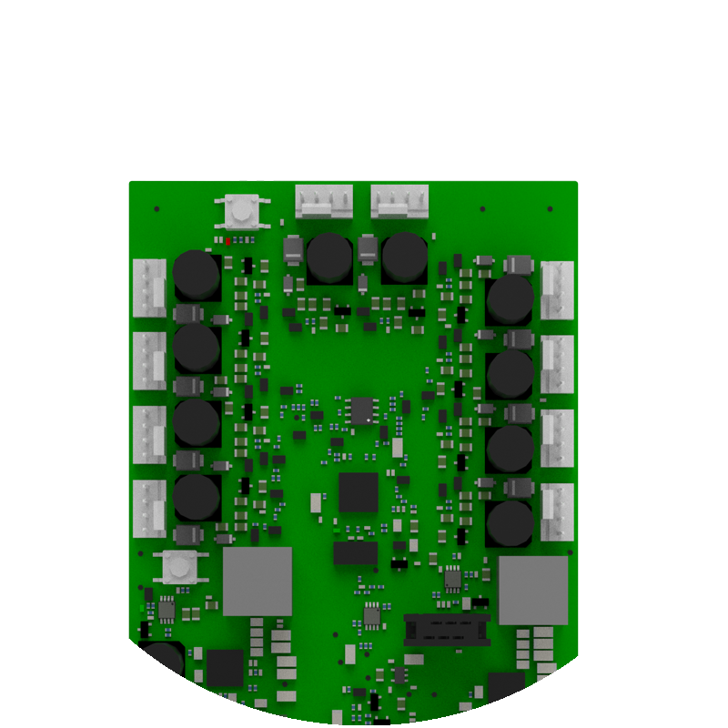
BMS Master Unit
The BMS Master Unit (BMU) board is the communications and control hub of Nilar’s BMS. The BMU is connected to the customers Energy Management System (EMS) and through this has the ability to control the contactors, communication with batteries, safety features and data sent to the EMS. The BMU has the overall control of all String Control Units in the system. Furthermore, the BMU can log data and enables remote updates of the BMS. Apart from this, the BMU controls the power and can get input data from several external devices such as contactors, insulation monitoring devices and residual current monitors.
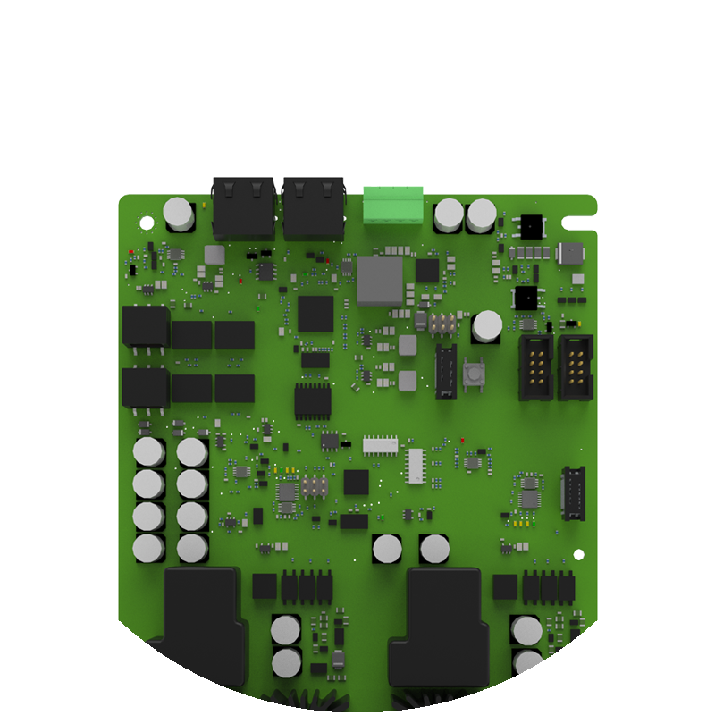
String Control Unit
The main use for the String Control Unit (SCU) is to connect and disconnect the strings, measure current in each string, measure voltage over each string switch and collect data from the Integrated Monitoring Unit (IMU). It also controls the Fan control unit (FCU), supplies 5V to the IMU and the FCU (not 24V for fans). It also provides the lower safety link from the IMUs and the FCU boards and the upper safety link between the SCU and the BMU board. Each SCU can handle up to 10 IMUs, equal to 10 battery packs, and 2 FCUs.
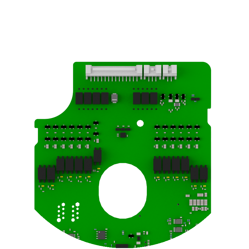
Integrated Monitoring Unit
The main purpose of the Integrated Monitoring Unit (IMU) board is to measure voltage, temperature, and pressure in the battery pack. To be able to monitor the data, the primary side of the IMU communicates with the SCU board. The secondary side is connected to the battery pack. The voltage monitors detect the voltage of each module and battery pack. An internal battery pressure sensor measures the relative pressure in each battery pack, relative to the outside. There is one temperature sensor in each battery pack, measuring at the midpoint of the battery pack. The communicated information also has the purpose to detect when a full charge cycle is completed.
Fan Control Unit
The Fan Control Unit (FCU) is used to control fans for cooling of packs. Each pack has its own fan and the FCU can control up to 10 fans. The FCU uses pulse-width modulation (PWM) to control fan speed and is designed for 12V DC fans with PWM control input and tacho output to monitor the speed of the fan. Each fan has its own control channel and can be controlled and monitored individually.
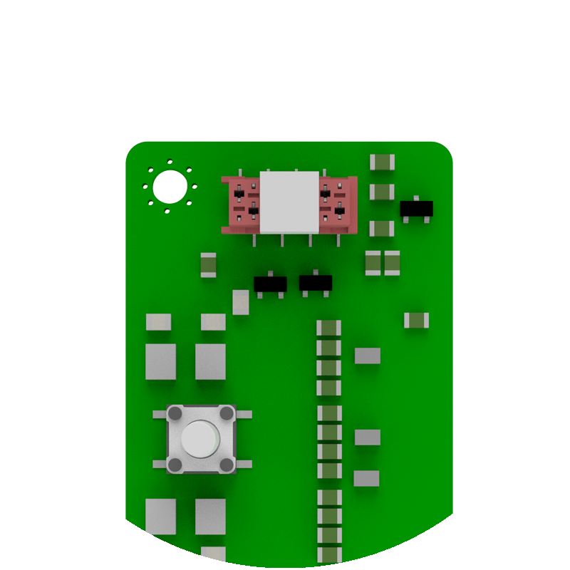
Humidity LED Interface
The Humidity LED Interface (HLI) board is designed to communicate through its on-board RGB LEDs to convey actions that the BMS is currently taking, and if any attention is required from an external party. It includes a tactile switch and measures the ambient temperature and relative humidity surrounding the card. The measurements and inputs are sent to the BMU which monitors the data and acts on user input.
Related pages

Safety

Sustainability
